Operating instructions for the woodworking machine IE 6009. I recommend it, very convenient, designed for a long operating time, does almost everything related to woodworking
The manufacturer of the combined woodworking machine IE-6009A is MogilevLiftMash, Mogilev, Website address: http://liftmach.by
OJSC "Mogilevliftmash" currently produces household woodworking machines IE-6009A2.1-02 and IE-6009A4.2-02. These machines perform the functions of longitudinal, transverse, and angled sawing, planing operations along a plane, along an edge, and at an angle. The IE-6009A2.1-02 machine performs a milling operation with a disk cutter (quarter selection).
The manufacturer of the combined woodworking machine IE-6009A is also JSC Plant Vetraz. Vitebsk region, Dokshitsky district, Begoml, Website address: http://zavod-vetraz.by/, which is part of the MogilevLiftMash holding.
IE-6009A2 combined woodworking machine. Purpose, scope
The IE-6009A woodworking machine is a compact desktop device for processing softwood and hardwood lumber.
The household woodworking machine is available in the following modifications:
- IE-6009A2- thickness of the sawn workpiece 45 mm, maximum planing width 200 mm
- IE-6009A2.1
- IE-6009A4.1- thickness of the sawn workpiece 85 mm, maximum planing width 280 mm
- IE-6009A4.2
- IE-6009A4.2-01- thickness of the sawn workpiece 95 mm, maximum planing width 280 mm
- IE-6009A2.1-02- thickness of the sawn workpiece 50 mm, maximum planing width 200 mm
- IE-6009A4.2-02- thickness of the sawn workpiece 95 mm, maximum planing width 280 mm
The machine performs the following operations of mechanical processing of wood:
- sawing along and across the grain;
- longitudinal sawing at an angle from 0 to 45°;
- jointing - planing (with a clamping device) along a plane with a processing width along the plane in one pass of up to 200 mm
- planing at an angle and along the edge;
- milling of grooves with disk and end mills;
- the IE-6009A2.1-02 machine performs a milling operation with a disk cutter (cutting a quarter);
- drilling from 3 to 16 mm;
The machine must be used in closed domestic premises, except residential ones.
The design according to the degree of moisture protection is unprotected.
The machine can operate under the following conditions.
- altitude above sea level - up to 1000 m;
- ambient temperature - from plus 5 to plus 40 °C;
- relative humidity of the surrounding air - no more than 80% at a temperature of plus 20 °C.
Design features of the woodworking machine IE-6009A
High power of the installed electric motor, which allows you to perform work with greater productivity.
Considerable attention in the design of machines is paid to the convenience and safety of operation:
- a thermal switch is installed in the motor windings of the IE-6009A2 and IE-6009A2.1 machines, protecting it from overheating;
- in the machines IE-6009A2.1, IE-6009A4.1, IE-6009A4.2 and IE-6009A4.2-01, an automatic switch is installed that protects the machine from overload and allows you to quickly disconnect it from the network;
- the machine has handles for moving it;
- the saw and disk cutter have guards; the disc cutter guard automatically closes after the workpiece passes the cutting zone;
- the casing enclosing the saw has a connection for connecting a dust extraction device (for example, a household vacuum cleaner) and a place for connecting a bag for collecting sawdust;
- When planing without a clamping device, the non-working part of the knife drum of the machine is covered with a special casing.
The machine's electric motor is powered and controlled from a single-phase alternating current network with a rated voltage of 230 V and a frequency of 50 Hz. The machines do not require permanent grounding.
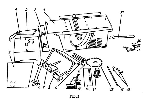
- Drive mechanism - 1 1 piece
- Ruler guide (without corners) - 2 1 pc.
- Protective device - 3 1 pc.
- Pressing device - 4 1 pc.
- Plate - 5 1 piece
- Corner plate - 6 1 piece
- Right bracket (with screws) - 7 1 pc.
- Left bracket (with screws and nuts) - 8 1 pc.
- Table - 9 1 piece
- Corner - 10 2 pcs
- Rod - 11 2 pcs
- Casing - 12 1 piece
- Housing - 13 1 piece
- Saw - 15 1 piece
- Template - 17 1 piece
- Screw (for fastening the guide bar) - 18 2 pcs.
- Bolt M8 x 50 GOST 7796-70 (for fastening the machine) - 24 2 pcs.
- Washer A8 GOST 11371-78 (on a bolt) - 24 4 pcs.
- Nut M8 GOST 15521-70 (on a bolt) - 24 2 pcs.
- Screw M6 x 16 GOST17475-80 - 25 2 pcs
- Nut M6 GOST 5915-70 (on a screw) - 25 2 pcs
- Washer A6 GOST 11371-78 (on screw) - 25 2 pcs
- Screw M4 x 8 GOST 1491-80 (for fastening the casing) - 26 2 pcs.
- Key 7811-4002 (S-32) - 30 1 pc.
- Earplugs LASER LITE LL-1 GOST 12.4.051-87 - 2 pcs.
- Instruction manual - 1 piece
IE-6009A General view of a combined woodworking machine


Design of the combined machine IE-6009A
The machine consists of the following mechanisms, components and devices:
- drive mechanism;
- clamping device;
- device for sawing and milling;
- protective device;
- table for drilling and milling.
Drive mechanism(Figure 2) consists of two aluminum walls 32 and 49 with bosses and holes for fastening these walls with threaded rods. The walls are designed to accommodate the bearings of the knife drum 35, the eccentric 40, the box 38 with capacitors, the base 72 with electrical devices placed on it, providing zero protection and protection from short circuit, covers 73 with buttons on it to turn the machine on and off. The walls have threaded holes for fastening devices. In the upper part of the walls there are threaded holes for fastening the plate, dovetail grooves for installing skis 39. In the lower part of the walls there are 8.5 mm holes and a T-shaped groove 9 mm wide (Figure 3) for attaching the machine to the workbench.
The drive belt is tensioned by turning the engine relative to the stud 33 and then fixing it with nuts 45. On the inside of the walls there are bosses for attaching the casing 37 to remove chips.
The leads from the motor stator windings (Figure 6) are connected to electrical equipment according to the diagram (Figure 7). The engine rotor 61 is mounted on two bearings 59 in the front and rear shields 58 and 62.
At the output end of the motor shaft, a drive pulley 48 is mounted on a key.
The transmission of torque to the knife drum is carried out using a V-belt 50.
The knives tilt in two grooves of the knife drum. The drum rotates on two rolling bearings 36. To prevent dust from entering, seals are installed in the bearing assembly cover.
At one end of the drum shaft, a driven pulley 42 is installed on a key. The pulley is secured against axial movements using a screw 43. The other end of the drum shaft is made conical for installing a conical bushing and cartridge.
The steel plate 56 is fixed to the walls of the machine. The aluminum ski 39 has dovetail grooves for moving it when adjusting the planing depth. The ski is moved by turning the eccentric with a 40mm wrench.
A casing 53 is installed on the mechanism, which prevents sawdust from getting into the ventilation windows of the engine when sawing and protects against injury. The clamping device 4 is installed on top of the machine and secured with two screws.
Pressing device 4 consists of a cast aluminum body with bosses for attaching two rods with brackets and springs, two axles with rollers and a cap screw for adjusting the clamping force. The maximum thickness of the processed material is 50 mm.

Sawing and milling device(see Figure 3) consists of a plate 5, a corner plate 6, brackets 7 and 8, rods 11. The plate 5 is fixed by means of brackets on the corner plate 6 and moves horizontally and vertically, and can be installed at an angle. The device is fixed using wing nuts 54 and nuts 55.
Protective device(Figure 3) consists of a knife 52 and a visor 51. The knife is secured to the wall boss using a wing nut 54 and is aligned with a special nut in the plane of rotation of the saw blade.
Drilling and milling table 9 (Figure 1) consists of an aluminum plate in which two guide rods are fixed. The table is installed on the corner plate 6.

The control symbols are marked on the machine casing (Figure 4).
Note: the product may have some design differences from the description and drawings due to its constant improvement.

Planing lumber on a plane (Figure 8)
To perform this operation:
- remove the conical sleeve 68 from the drum shaft 35 using a round nut 67 (Figure 5) and a key 30, having previously stopped the rotation of the drum with a wooden plank inserted into its groove, and unscrewing the bolt 71 securing the conical sleeve;
- install the casing 13 (Figure 1), set the desired planing depth, to do this, release the locking screws 41 (Figure 2) of the ski, turn the eccentric with a wrench 27, setting the ski to the desired planing depth, secure with the locking screws;
- Check the correct installation and reliability of the knives on the knife drum.
The correct installation of the knives is checked using template 17 (Figure 1), pressed with its edge against the steel plate 56. When turning the knife drum, correctly installed knives should lightly touch the edges of the cutting edge to the bottom edge of the template. After alignment, tighten the bolts of the wedges securing the knives securely.
The knives, wedges and bolts installed by the manufacturer in a balanced knife drum are completely matched by weight. To avoid imbalance of the knife drum and vibration, it is prohibited to transfer parts from one set to another.
Install the clamping device so that the direction of material supply, indicated on plate 66 of the clamping device body, is towards the steel plate 56. Securely attach the clamping device to the jointing mechanism with the screws located in the holes of the housing. Using the head 65 located on top of the device, set the pressure rollers 64 to the desired thickness of the workpiece.
When planing short pieces of lumber, be sure to use an additional block to push the lumber, and the worker should always be to the left of the processing area, and not behind the processed lumber.
Planing lumber at an angle and along the edge (Figures 9 and 10)
To perform this operation:
- install the protective casing 12 so that the working part of the drum remains open only to the width of the material surface being processed;
- install the guide 2 corners 10 on the ruler, secure them with wing nuts 54, then install the casing 13, covering the protruding part of the rotating drum;
- set the guide ruler at the desired planing angle and secure it to the steel plate and ski using 18 screws and washers. When planing lumber along the edge, turn the guide ruler at an angle of 90° with respect to the steel plate 56 and ski 39.
ATTENTION! When performing these operations, be careful when the material being processed comes out, since the upper area of the cutting knives is not closed from touch.
Sawing lumber along and across the grain (Figure 11)
To perform this operation:
- install the conical bushing 68 (Figure 5) on the shaft of the drum 35, having previously stopped the rotation of the drum with a wooden plank inserted into its groove, and wedge it between the ski 39 (Figure 3), install the washer 70 and secure with bolt 71 (Figure 5);
- install saw blade 15 (Figure 1), designed for longitudinal and transverse sawing of lumber, onto the bushing and securely fasten it with nut 68 (Figure 5);
- set a lower (2200) number of drum revolutions (the manufacturer produces the machine with a set maximum speed of 5000), for which remove the cover 44, loosen the nut 45 (Figure 2) fixing the motor, turn the motor to loosen the belt, remove and move it to a groove of a larger diameter of the drum pulley and into a groove of a smaller diameter of the engine pulley; if necessary, use nuts 45 to align the pulleys in the same plane (permissible displacement of the axes of the grooves is no more than 0.4 mm); by turning the engine relative to the stud 33, tighten the belt, then tighten the nut 45, install the cover 44, close the drum with casing 12 (Figure 1); - install plate 5 and screw it with two screws 25 to steel plate 56 and ski 39 with M6 nuts and washers; so that the plate does not deform during operation, install wooden pads 4.5 mm thick between it, the ski 39 and the steel plate at both ends of the plate;
- install the protective device 3 on the boss so that the knife of the device is in the same plane with the saw blade, adjust using a special nut, secure the knife with a wing nut 54 (Figure 3);
- Install ruler 2 on plate 5, set it to the desired cutting width of the board parallel to the plane of the saw blade and secure it with screws 18 (Figure 1) with washers.
Feed the board evenly at a speed of no more than one meter per minute.
When sawing across long workpieces, the guide ruler must be removed.
Sawing to a certain cutting depth (Figure 12)
To perform this operation:
- close the drum with a protective casing 12, screw two brackets 7 and 8 with nuts and grooves to the plate 5 on the left side of the plate;
- screw two guide rods 11 into the upper threaded holes of wall 32, install corner plate 6 on them and lock the guide rods with M16x1.5 nuts; Align the slab to the required cutting depth and secure with nuts 55 and wing nuts 54.
- To increase the stability of plate 5, it is necessary to lay wooden pads between the plate and the ski at both ends of the plate, with a thickness depending on the set cutting depth.
- ATTENTION! When selecting a quarter, be careful because the top area of the saw blade is not covered by the guard visor.
Sawing lumber at an angle (Figure 13)
Screw two guide rods 11 into the lower threaded holes of the wall, installing corner plate 6 on them and locking the guide rods with M16x1.5 nuts.
Align plate 5 to the desired angle and lock the sectors and guide plates with wing nuts 54.
Milling grooves (Figure 14)
To perform this operation:
- install cone bushing 68 (see description in Figure 11). Install cutter 19 on the conical bushing (wood-cutting groove cutters GOST 11290-80E with a diameter of 125 mm, a mounting hole with a diameter of 32 mm, a width of 8-12 mm) (Figure 14), having previously stopped the rotation of the drum with a wooden plank, and secure the cutter with a nut 69;
- set the guide ruler 2 to the required size from the side plane of the cutter by using the corners of the ruler, as well as to the desired milling depth by raising or lowering the slab.
- Pressing the workpiece against the plate and the side plane of the ruler, feed uniformly at a speed of 1 to 1.5 m/min.
Drilling and milling slots (Figure 15)
To perform these operations:
- remove the conical sleeve 68 from the drum shaft (see description to Figure 8) - install chuck 23 (chuck 16-B18 GOST 8522-79 or factory-made drill chuck PS-16.00.00) and secure it with bolt 71;
- close the drum with protective casing 12 and secure it with screws;
- screw two guide rods 11 into the lower threaded holes of wall 32, install corner plate 6 on them and lock the guide rods 11 with nuts;
- install a 6th corner table for drilling and milling on the slab;
- fix a drill (twist wood-cutting drills with cylindrical shanks with a diameter of 3 to 16) or a cutter (wood-cutting end cutters GOST 8994-80 with a diameter of 3-16 mm) in the drill chuck;
- adjust the table for drilling and milling in height relative to the tool and secure it with wing nuts 54;
- lock corner plate 6 using nuts 55.
Drilling and milling are carried out according to the markings. Feeding is carried out by moving the material being processed along the table.
Electrical circuit diagram of the combined woodworking machine IE-6009A

Electric motor type - Asynchronous single-phase with working and starting capacitors.
IE-6009A. Video
Technical characteristics of the combined machine IE-6009A
| Parameter name | IE-6009 A2 |
IE-6009 A2.1 |
IE-6009 A4.1 |
IE-6009 A4.2 |
IE-6009 A4.2-01 |
IE-6009 A2.1-02 |
IE-6009 A4.2-02 |
|---|---|---|---|---|---|---|---|
| Operations performed on the machine | |||||||
| Sawing longitudinal, transverse | + | + | + | + | + | + | + |
| Planing along a plane, along an edge | + | + | + | + | + | + | + |
| Sawing at an angle | + | - | - | - | - | + | + |
| Milling with a disk cutter (quarter selection) | + | + | - | - | + | + | - |
| Drilling | + | - | - | - | + | + | + |
| Milling with a cylindrical (face) mill | + | - | - | - | + | + | + |
| Basic machine parameters | |||||||
| Thickness of the sawn workpiece, mm | 45 | 50 | 85 | 95 | 95 | 50 | 95 |
| Maximum jointing (planing) width, mm | 200 | 200 | 280 | 280 | 280 | 200 | 280 |
| Maximum depth of layer removed in one pass when planing, mm | 2,4 | 3,0 | 3,0 | 3,0 | 3,0 | 3,0 | 3,0 |
| Knife drum rotation speed at idling, rpm | 5000 | 5000 | 5400 | 5400 | 5400 | 5000 | 5400 |
| Saw rotation speed at idle speed, rpm | 2200 | 2200 | 2300 | 2300 | 2300 | 2200 | 2300 |
| Number of planing knives | 2 | 2 | 2 | 2 | 2 | 2 | 2 |
| Drilling | |||||||
| Drill shank diameter, mm | 3..16 | - | - | - | 3..16 | 3..16 | 3..16 |
| Shank diameter for drill chuck installation, mm, mm | Morse taper B18 | - | - | - | Morse taper B18 | Morse taper B18 | Morse taper B18 |
| Electrical equipment of the machine | |||||||
| Type of supply current | 220V 50Hz | 220V 50Hz | 220V 50Hz | 220V 50Hz | 220V 50Hz | 220V 50Hz | 220V 50Hz |
| Number of electric motors on the machine, pcs. |
Model IE6009 A2 is a woodworking machine that must be installed on a table. The machine is distinguished not only by its compactness, but also by its versatility, which is why this model, although it belongs to household machines, is also perfect for work in small woodworking workshops.
Machine Features
The Mogilevliftmash IE6009 A2 machine is adapted for planing wood both in normal mode and at a given angle or along the edge of the workpiece; moreover, the use of the machine for planing makes it possible to use a clamping device if the thickness of the workpiece is less than 45 mm. Using this model, an operation such as sawing is also available, which can be performed both along and across the wood fibers. When performing sawing work, the machine operator can set the sawing angle; it is adjusted manually and can reach 45 degrees. The machine also has all the capabilities for additional installation of a disk cutter and a protective casing for it, with which you can perform milling or drilling work.
The motor installed on the Mogilevliftmash IE6009 A2 has a long service life, but in order to avoid overheating and resulting breakdowns, a thermal switch is installed in the motor winding.
For safe operation, disc cutters and saws have protective guards; moreover, after the workpiece passes the processing zone, the shutter near the disc cutter is lowered automatically. Also, for safety and precision of work, the machine has a connection for a dust cleaning device (even a household vacuum cleaner can be connected to the machine).
If the clamping device is not used during planing work, then the non-working part of the drum is covered with a special casing, which is included in the kit.
Mogilevliftmash IE6009 A2 operates from a 220 V network, so it does not require grounding, which also indicates its transportability; for this purpose, it is provided on the outside of the handle frame.
Specifications
The Mogilevliftmash IE6009 A2 machine is equipped with a motor with a power of 1700 W, its power provides 5000 revolutions of the drum, and the saw rotates at a frequency of 2200 revolutions.
The planing depth of the machine does not exceed 2.4 mm, while in one pass the drum with blades captures up to 200 mm of workpiece. When performing drilling work, the machine operator can adjust the diameter of the hole, varying it from 3 to 16 mm.
The dimensions of Mogilevliftmash IE6009 A2 with tools and accessories are 700x670x420 mm, while the weight of the machine is 60 kg. If you remove the removable accessories from the machine, then its weight will be 42 kg, which means that this model is light and easy to transport.
The woodworking machine IE 6009 A2 "Mogilev" 1.7 kW is designed for: planing with a clamping device along the plane with a workpiece thickness of no more than 50 mm; planing at an angle and along the edge; sawing along and across the fibers; longitudinal cutting at an angle from 0 to 45 degrees; milling grooves with a disk cutter (if you purchase a disk cutter and a protective casing for it).
Power, W:1700
Voltage, V:220
Motor type: asynchronous
Max planing width, mm: 200
Max planing depth, mm: 2.4
Max thickness of workpiece with clamping device, mm: 50
Max cutting depth, mm: 45
Outer diameter of the disk, mm: 200
Disc mounting diameter, mm: 32
Idle speed, rpm: 2200,5000
Max drill diameter, mm: 16
Planing: yes
Thickening: yes
Quarter sampling: no
Sawing: yes
Drilling/milling: yes
Dimensions (LxWxH), mm: 740x510x470
Weight, kg:53
Ch. 53/2.4mm, disc 200x32mm, knife 200mm, 2200/5000rpm, 38 kg
Reviews
aleksandr81
I recommend it, very convenient, designed to last for a long time, does almost everything in woodworking
Great!Optimal for home. According to the passport, the operating mode is long. If used correctly, no problems. The main thing is to read the instructions. We bought the machine, read the instructions, saw that before starting operation you need to turn it on for 30 minutes (at idle speed), then you need to TIGHTEN the belt. When planing/cutting, change the belt (as in other machines) Unlike Chinese/Russian crafts, it has maximum weight and a rigid frame design; the larger the table, the higher the quality of planing Noalexeykov
Normal machine for home use
FineA month ago we bought this machine to help us. Because He came to us after setting up the formwork at the construction site of the house; we haven’t been able to try it to the fullest yet. But we use it from time to time, and I will say that we like his work. We have read a lot of unflattering reviews about machines from this domestic manufacturer, but so far we have not identified any obvious “jambs”) and this is encouraging. Its main disadvantage, as it seemed to us, is the time spent on changing the operation, but since... The machine is more for home use, then we consider this normal. The machine has plastic pulleys, but this is easy to fix if you have a normal turner you know. Made in RBSimplicity of design Operation changeover timePlastic pulleysariog
Will doA similar machine at work, only without an upper stand, in general the machine is rather weak, cutting more than 40 mm will cause problems, the pulley is weak, gets hot, stretches, needs to be modified, the saw is not convenient, the guide is clumsy, the only plus is that it planes well Plans well Sawing on him is tormentdfvgbh1990
fulfills its functions
Will doIt turns on/off, planes, saws... Time will tell the reliability of the plastic pulleys... and everything else. But basically, for that kind of money, what more could you want. price. Plastic pulleys.Dmitry
